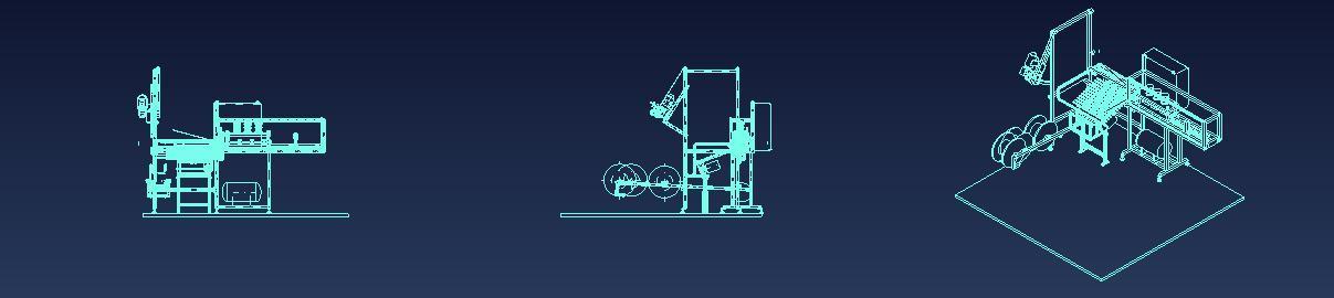
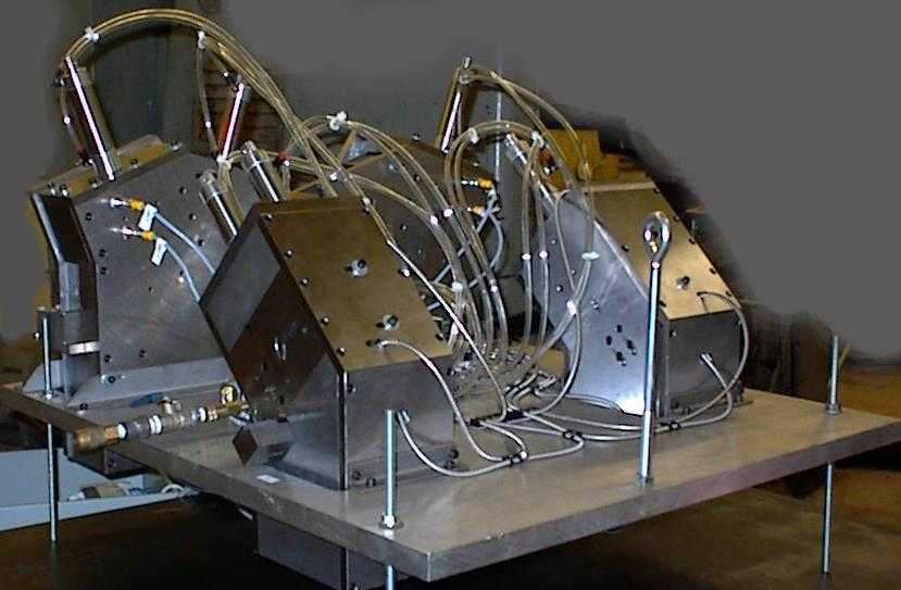
This type die is perhaps the ultimate in operator safety. There are no powered moving parts that the operator can contact. All moving parts are totally enclosed. Figure 1 shows four such dies attached to a mounting plate that will be placed on to a larger machine. These dies have shaped holes that match the profile of the extrusion to be trimmed. When the extrusion is inserted into the shaped (mouse hole) orifice until it contacts the internal stop, the PLC and sensors detect that it is in place and initiate the cycle. This set of four dies trims both ends of the right hand and left hand part configuration.
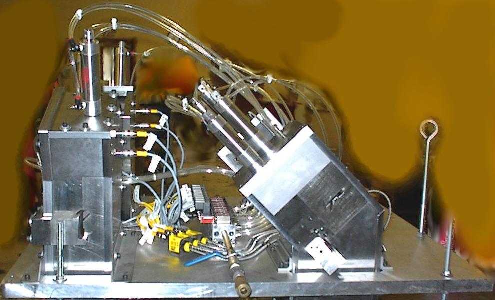
Figure 2 shows a little more detail of the air valves, plumbing, and sensors that control and actuate the mechanism.
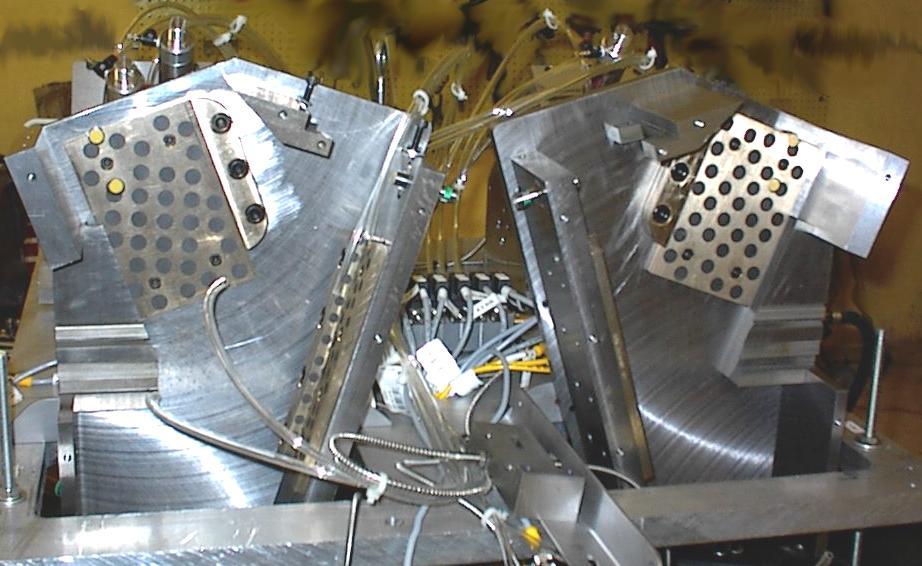
Two of these dies are required to make diagonal cuts in two different directions. This required two different knives that had to be sequenced because in the forward position, each knife occupied the space required for the other knife in the forward position. Figure 3 shows the dies that make the double cut partially disassembled showing the gibs and wear plates that guide and restrain the knives.
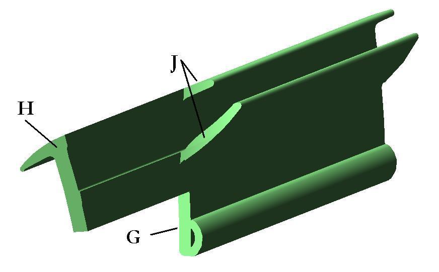
Figure 4 shows a computer model of the finished trim on the end of one of the extrusions. The cut marked G was made in an earlier operation, when the extrusion was cut to length. The trim at H was made by one of the two knives mounted in the dies shown in Figure 3. The cut marked J was performed by the second knife
Since two different cuts were required in this case, the extrusion was clamped in the die before the first cut was made and released only after the second cut was made.